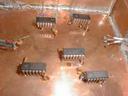
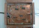
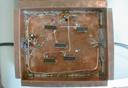
| [134] 3aui00.jpg |
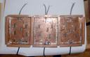 |
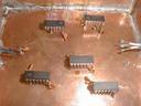
| 3 AUI's with chips and their blocking capacitor installed
| |
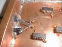
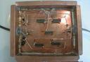
| [135] 3aui01.jpg |
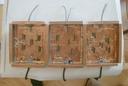 |
| 3 AUI's with chips and their blocking capacitor installed
| |
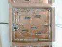
| [136] 3aui02.jpg |
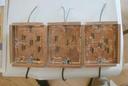 |
| 3 AUI's with chips and their blocking capacitor installed
| |
| [137] aui00.jpg |
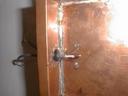 |
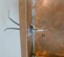
| Wires for connecting the wire nut
| |
| [138] aui01.jpg |
 |
| Wires for connecting the wire nut
| |
| [139] aui02.jpg |
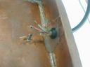 |
| AUI cable
| |
| [13a] aui03.jpg |
 |
| AUI cable (left), signal cable (right)
| |
| [13b] aui04.jpg |
 |
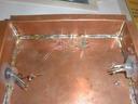
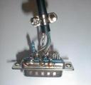
| Chips and their blocking capacitors in AUI
| |
| [13c] aui05.jpg |
 |
| Chips and their blocking capacitors in AUI
| |
| [13d] aui06.jpg |
 |
| Chips and their blocking capacitors in AUI
| |
| [13e] aui07.jpg |
 |
| Chips and their blocking capacitors in AUI
| |
| [13f] aui08.jpg |
 |
| Chips and their blocking capacitors in AUI
| |
| [140] aui09.jpg |
 |
| Chips and their blocking capacitors in AUI
| |
| [141] aui10.jpg |
 |
| Chips and their blocking capacitors in AUI
| |
| [142] aui11.jpg |
 |
| Chips and their blocking capacitors in AUI
| |
| [143] aui12.jpg |
 |
| Chips and their blocking capacitors in AUI
| |
| [144] aui_box_3d.jpg |
 |
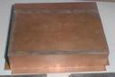
| AUI with lid
| |
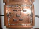
| [145] aui_box_closed.jpg |
 |
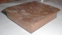
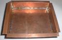
| Undrilled AUI box
| |
| [146] aui_box_double_soldering.jpg |
 |
| Soldering the AUI box
| |
| [147] aui_box_drilling.jpg |
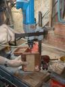 |
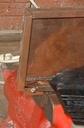
| Drilling out the AUI box
| |
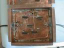
| [148] aui_box_inside.jpg |
 |
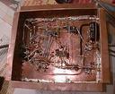
| AUI box, inside view
| |
| [149] aui_box_soldering.jpg |
 |
| Soldering a corner of AUI box
| |
| [14a] aui_bushing.jpg |
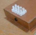 |
| Instead of 4 terminals there should be 6
| |
| [14b] aui_bushings0.jpg |
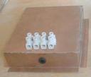 |
| Instead of 4 terminals there should be 6
| |
| [14c] aui_connector.jpg |
 |
| AUi connector
| |
| [14d] aui_gluing.jpg |
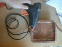 |
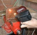
| Fixing the wires with thermal glue
| |
| [14e] complete_aui0.jpg |
 |
| Complete AUI interface
| |
| [14f] complete_aui1.jpg |
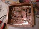 |
| Complete AUI interface
| |
