| [16f8] dscn0645.jpg |
 |
| |
| [16f9] dscn0646.jpg |
 |
| |
| [16fa] dscn0646_e.jpg |
 |
| |
| [16fb] dscn0646_e2.jpg |
 |
| |
| [16fc] dscn0647.jpg |
 |
| |
| [16fd] dscn0648_e.jpg |
 |
| |
| [16fe] dscn0649_e.jpg |
 |
| |
| [16ff] dscn0650.jpg |
 |
| |
| [1700] dscn0651.jpg |
 |
| |
| [1701] dscn0652.jpg |
 |
| |
| [1702] dscn0653.jpg |
 |
| |
| [74] ronja1-17.jpg |
 |
| |
| [75] ronja1-17s.jpg |
 |
| |
| [76] ronja1-18.jpg |
 |
| |
| [77] ronja1-18s.jpg |
 |
| |
| [78] ronja1-19.jpg |
 |
| |
| [79] ronja1-19s.jpg |
 |
| |
| [7a] ronja1-20.jpg |
 |
| |
| [7b] ronja1-20s.jpg |
 |
| |
| [7c] ronja1-21.jpg |
 |
| |
| [7d] ronja1-21s.jpg |
 |
| |
| [7e] ronja1-22.jpg |
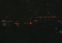 |
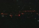
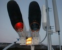
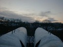
| Node Andel shining in the darkness.
| |
| [7f] ronja1-22s.jpg |
 |
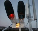
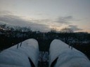
| Node Andel shining in the darkness.
| |
| [80] ronja1-23.jpg |
 |
| |
| [81] ronja1-23s.jpg |
 |
| |
| [82] ronja1-24.jpg |
 |
| |
| [83] ronja1-24s.jpg |
 |
| |
| [84] ronja1-25.jpg |
 |
| |
| [85] ronja1-25s.jpg |
 |
| |
| [86] ronja1-26.jpg |
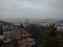 |
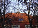
| View of prague from Bakulak
| |
| [87] ronja1-26s.jpg |
 |
| |
| [88] ronja1-27.jpg |
 |
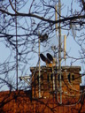
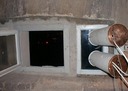
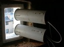
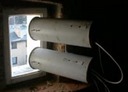
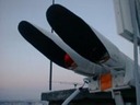
| Installation on node Andel
| |
| [89] ronja1-27s.jpg |
 |
| |
| [8a] ronja1-28.jpg |
 |
| Installation on node Andel
| |
| [8b] ronja1-28s.jpg |
 |
| |
| [8c] ronja1-29.jpg |
 |
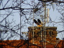
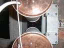
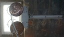
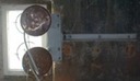
| Transmitter of Andel node
| |
| [8d] ronja1-29s.jpg |
 |
| |
| [8e] ronja1-30.jpg |
 |
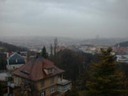
| Looking northward
| |
| [8f] ronja1-30s.jpg |
 |
| |
| [90] ronja1-31.jpg |
 |
| Bakulak in the distance
| |
| [91] ronja1-31s.jpg |
 |
| |
| [e6c] smichov.jpg |
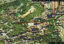 |
| Source: map on http://czfree.net
| |
| [92] soldering0.jpg |
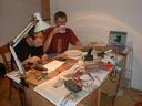 |
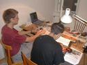
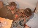
| JBohac (left) and Clock (right)
| |
| [93] soldering1.jpg |
 |
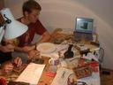
| Clock (left) and JBohac (right)
| |
| [94] soldering2.jpg |
 |
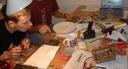
| JBohac (left) and Clock (right)
| |
| [95] soldering3.jpg |
 |
| JBohac, doing the final circuit check after soldering.
| |
| [96] soldering4.jpg |
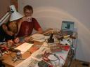 |
| JBohac (left) and Clock (right)
| |
| [97] testing00.jpg |
 |
| Clock (left) and Krynn (right)
| |
| [98] testing01.jpg |
 |
| Clock (left) and Krynn (right)
| |
| [99] testing02.jpg |
 |
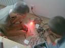
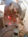
| Clocking is checking the maximum RSSI voltage
| |
| [9a] testing03.jpg |
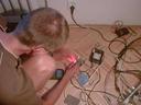 |
| Clock, measuring the carrier frequency.
| |
| [9b] testing04.jpg |
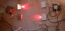 |
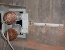
| Ronja test setup on the floor
| |
| [9c] testing05.jpg |
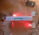 |
| We tried to separate the optical paths but it made no difference.
| |
| [9d] testing06.jpg |
 |
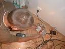
| Clock, measuring the RSSI
| |
| [9e] testing07.jpg |
 |
| Created with The GIMP
| |
| [9f] testing08.jpg |
 |
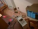
| Ronja test setup on the ground
| |
| [a0] testing09.jpg |
 |
| Ronja test setup
| |
| [a1] testing10.jpg |
 |
| Ronja test setup
| |
| [a2] testing11.jpg |
 |
| Ronja setup on the ground
| |
| [a3] testing12.jpg |
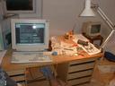 |
| A computer connected to the Internet
| |
